Week 3:
Schematic:

Arduino Code:
int lightCutoff = 600;
//Photocells
int sensor0Pin = A0;
int sensor0Value = 0;
int sensor1Pin = A1;
int sensor1Value = 0;
int sensor2Pin = A2;
int sensor2Value = 0;
int sensor3Pin = A3;
int sensor3Value = 0;
int sensor4Pin = A4;
int sensor4Value = 0;
//Player 1 score
int p1s1 = 11;
int p1s2 = 10;
int p1s3 = 9;
int p1s4 = 8;
int p1s5 = 7;
//Reset Buttom
int resetPin = 13;
int resetState = 0;
//Game Over Sensor
int gameoverPin = A5;
int gameoverValue = 0;
int THRESHOLD = 100;
//Buzzer
int buzzPin = 2;
#define NOTE_C6 1047
#define NOTE_D6 1175
#define NOTE_E6 1319
#define NOTE_F6 1397
void setup() {
Serial.begin(9600);
pinMode(p1s1, OUTPUT);
pinMode(p1s2, OUTPUT);
pinMode(p1s3, OUTPUT);
pinMode(p1s4, OUTPUT);
pinMode(p1s5, OUTPUT);
pinMode(buzzPin, OUTPUT);
digitalWrite(p1s1, LOW);
digitalWrite(p1s2, LOW);
digitalWrite(p1s3, LOW);
digitalWrite(p1s4, LOW);
digitalWrite(p1s5, LOW);
pinMode(resetPin, INPUT);
}
void loop() {
//Reset Score Bottom
resetState = digitalRead(resetPin);
if (resetState == HIGH) {
digitalWrite(p1s1, LOW);
digitalWrite(p1s2, LOW);
digitalWrite(p1s3, LOW);
digitalWrite(p1s4, LOW);
digitalWrite(p1s5, LOW);
}
//Game over sensor
gameoverValue = analogRead(gameoverPin);
if (gameoverValue >= THRESHOLD) {
tone(buzzPin, NOTE_F6, 500);
delay(100);
tone(buzzPin, NOTE_D6, 500);
delay(100);
tone(buzzPin, NOTE_C6, 1000);
digitalWrite(p1s1, HIGH);
digitalWrite(p1s2, HIGH);
digitalWrite(p1s3, HIGH);
digitalWrite(p1s4, HIGH);
digitalWrite(p1s5, HIGH);
delay(200);
digitalWrite(p1s1, LOW);
digitalWrite(p1s2, LOW);
digitalWrite(p1s3, LOW);
digitalWrite(p1s4, LOW);
digitalWrite(p1s5, LOW);
delay(200);
digitalWrite(p1s1, HIGH);
digitalWrite(p1s2, HIGH);
digitalWrite(p1s3, HIGH);
digitalWrite(p1s4, HIGH);
digitalWrite(p1s5, HIGH);
delay(200);
digitalWrite(p1s1, LOW);
digitalWrite(p1s2, LOW);
digitalWrite(p1s3, LOW);
digitalWrite(p1s4, LOW);
digitalWrite(p1s5, LOW);
}
//Start of Counter & Photocells
sensor0Value = analogRead(sensor0Pin);
sensor1Value = analogRead(sensor1Pin);
sensor2Value = analogRead(sensor2Pin);
sensor3Value = analogRead(sensor3Pin);
sensor4Value = analogRead(sensor4Pin);
//Serial.println(sensor0Value);
//Serial.println(sensor1Value);
//Serial.println(sensor2Value);
//Serial.println(sensor3Value);
//Serial.println(sensor4Value);
if(sensor0Value <= 800)
{
digitalWrite(p1s1, HIGH);
//Serial.print("One");
}
else if(sensor1Value <= lightCutoff)
{
digitalWrite(p1s2, HIGH);
//Serial.print("Two");
}
else if(sensor2Value <= lightCutoff)
{
digitalWrite(p1s3, HIGH);
//Serial.print("Three");
}
else if(sensor3Value <= lightCutoff)
{
digitalWrite(p1s4, HIGH);
//Serial.print("Four");
}
else if(sensor4Value <= 750)
{
digitalWrite(p1s5, HIGH);
//Serial.print("Five");
}
else
Serial.print("end");
//End of Counter & Photocells
}
Week 2:
Concept Image:

Main Idea/ Functions:
The whole game works like a pinball machine. You have a launcher that shots the marble up the ramp, while the marble goes up LEDs will light up as you go higher, also there will be a digital score board at the top which will keep track of the highest score so far. If the player hits the top two red LEDs will turn on, to signal your lose.
Goal of the Game:
The goal of the game is to get as close as possible to the top of the ramp without hitting the top. Hitting the top will count as a lose.
Rules to the Game:
1- Each player has 3 tries.
2- Hitting the top will count as a lose.
3- The launcher is the only tool you can use to launch the marble.
4- Have fun.
Week 1:
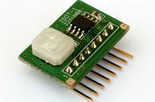
Sensor Name:
ZDots
Manufacturer
& Part Number: Zilog SBC 3201888
Researcher
Names: Unknown
Image of
Sensor:
Describe the
main function of the sensor:
- Complete, fully functional motion detection SBC including Fresnel lens
- Comes pre-programmed with motion detection software
- Sensitivity control via simple hardware configuration
- Advanced serial (UART) based configuration and interface
- SLEEP mode for low power applications
- No temperature compensation required
- Input to support CDS photocell input for ambient light detection
- Minimal components ensure highest possible Mean Time Between Failures (MTBF)
- Application code can also be modified to support custom solutions
- Complete development system available
Example of
applications in the real world:
- The sensor can be used to make a machine follow a specific colored line. Making the machine act like it’s on a track, like a train.
- Can use the sensor as motion detector. (Example: Security System)
Electrical
Characteristics of the sensor:
- Small form factor—25.5 mm x 16.7 mm
- Wide 5 m x 5 m, 60 degree detection pattern Operates from 2.7 V to 3.6 V power supply
- Simple 8-pin interface
- Standard operating temperature: 0 °C to 70 °C
Schematic Diagram of
Sensor & Arduino Wiring:
Wiring and Pin diagrams


Additional parts needed for proper operation
N/A
Provide a
code sample for reading the sensor:
//Motion
Detector
#define DEV_ADDR 1
#define DATA_IN_EP 1
#define DATA_OUT_EP 2
#define INTERRUPT_EP 3
#define CONFIG_NUM 1
#define SLEEP_MODE_PIN 4
#define MOTION_DETECT_PIN 2
int val;
void setup()
{
Serial.begin( 115200 );
Serial.println("Start");
delay( 200 );
//PIR related
digitalWrite(SLEEP_MODE_PIN, HIGH);
}
void loop()
{
val = digitalRead(MOTION_DETECT_PIN);
//the ePIR sensor is active low so if motion
is detected the output is low
if(val == LOW)
Serial.println("DETECTED");
else
Serial.println("NON DETECTED");
}
References /
Bibliography:
Conceptual
Application:
We can integrate the sensor into a laser mouse.
Giving the mouse accurate movement, also mouse pads can be fabricated with a
certain colored pattern on it, making it possible to create a straight line,
circles and other shapes with ease. This would give the mouse a secondary
component to it, which be used as a drawing tool, and also as a tracker.
No comments:
Post a Comment